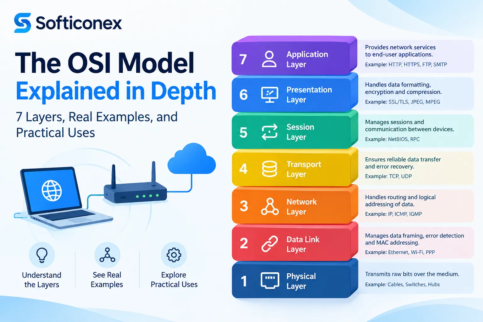
The OSI (Open Systems Interconnection) model is the conceptual backbone of how we understand computer networking. Almost every article on the topic repeats the same seven-layer diagram and a mnemonic like “Please Do Not Throw Sausage Pizza Away.” That’s the surface level. This guide goes deeper covering not just what each layer is, but how data actually moves through it, how to troubleshoot problems at each layer, what security risks live at each layer, and how the OSI model maps to the protocols you actually use every day.
1. What Is the OSI Model, and Why Was It Created?
The OSI model was developed by the International Organization for Standardization (ISO) and published in 1984 as a universal set of rules for how computer systems should communicate over a network, regardless of their underlying architecture or manufacturer.
Before OSI, the biggest problem in computing was vendor lock-in at the network level. IBM, DEC, and other manufacturers each had proprietary networking stacks (like IBM’s SNA) that couldn’t talk to each other. ISO’s goal was to create a reference model not a protocol itself, but a common language and structure that any vendor could build compatible systems against.
Important nuance most articles skip: the OSI model was never fully adopted as an actual protocol suite. The OSI protocol stack (X.25, CLNP, etc.) largely lost out commercially to TCP/IP in the 1990s. What survived and what you use today is the model as a conceptual and diagnostic framework, not the original OSI protocols themselves. This is why the OSI model and TCP/IP model coexist: TCP/IP is what’s actually running on the wire; OSI is the mental map we use to talk about it, teach it, and troubleshoot it.
The Official Standard Behind It
The formal specification is ISO/IEC 7498-1, first published in 1984 and later ratified jointly with the CCITT (now the ITU-T) as recommendation X.200. This joint ISO/CCITT effort is a detail almost every beginner article omits the model wasn’t purely an ISO product, it was a negotiated standard between the computing industry (ISO) and the telecommunications industry (CCITT), which is part of why it has strong roots in circuit-switched telecom thinking (particularly visible in the Session and Presentation layers, which have no strong equivalent in the leaner, more pragmatic TCP/IP model built by ARPANET engineers around the same period).
OSI vs. the ARPANET Philosophy
TCP/IP grew out of a “rough consensus and running code” engineering culture (Vint Cerf, Bob Kahn, and the IETF). OSI grew out of a formal, top-down standards-committee process. This cultural difference is why TCP/IP won in practice when it shipped working code years before OSI-compliant products were commercially viable while OSI won as the teaching model because its seven-layer separation of concerns is pedagogically cleaner than TCP/IP’s four collapsed layers.
2. The Seven Layers of OSI Model Full Breakdown
Each layer has a specific job, a specific Protocol Data Unit (PDU) name (a detail many articles get wrong or omit), typical protocols, and typical hardware/software associated with it.
Layer 7 Application Layer
- PDU: Data
- Function: The layer closest to the end user. It’s where software applications interact with the network, not the applications themselves, but the interface between the app and the network stack.
- Protocols: HTTP/HTTPS, FTP, SMTP, DNS, DHCP, Telnet, SSH
- Real-world example: When you type a URL into a browser, the browser uses HTTP/HTTPS at this layer to structure the request.
- Common misconception: People think the “application” itself (like Chrome or Outlook) is Layer 7. It’s not the application that uses Layer 7 protocols; the app itself sits above the OSI stack entirely.
- Extended protocol list (rarely covered in full): IMAP, POP3, SNMP, NTP, LDAP, RDP, SMB/CIFS, NFS, MQTT (increasingly important for IoT), WebSocket, gRPC (built on HTTP/2).
- Modern relevance: REST APIs, GraphQL, and gRPC, the backbone of nearly all modern web and mobile apps all operate as Layer 7 constructs on top of HTTP. Almost no beginner article connects “the OSI model” to “how a mobile app talks to its backend,” even though this is one of the most practically relevant applications of the concept for developers researching the topic.
Layer 6: Presentation Layer
- PDU: Data
- Function: Translates data between the application format and the network format. Handles encryption/decryption, compression, and character encoding (like ASCII, EBCDIC, UTF-8).
- Protocols/Standards: SSL/TLS (partially this is debated, see below), JPEG, MPEG, GIF encoding formats
- Overlooked detail: Most modern discussions place TLS encryption at Layer 6, but in practice, TLS operates between Layer 4 and Layer 7 in real implementations, wrapping around the transport layer socket. The “cleanliness” of assigning TLS strictly to Layer 6 is a textbook simplification real-world engineers usually just say “TLS operates at the transport/session boundary.” This nuance is almost never explained clearly in beginner content.
Layer 5: Session Layer
- PDU: Data
- Function: Establishes, manages, and terminates connections (sessions) between two devices. Handles session checkpoints, synchronization, and dialogue control (who talks when full-duplex vs half-duplex).
- Protocols: NetBIOS, RPC, PPTP, SIP (used in VoIP call setup)
- Real-world example: When you’re on a video call, the session layer is what keeps track of the ongoing “conversation” state even if packets are lost, the session layer knows the call is still active and can resume.
- Gap in most articles: Session layer’s role in API session tokens and cookies for web apps is rarely mentioned, even though logically, maintaining a “logged-in” state across multiple HTTP requests is a session-layer concept, even though in the TCP/IP world it’s actually implemented at Layer 7 via cookies/tokens (since HTTP is stateless). This is a great example of where the OSI model’s clean separation doesn’t match real implementation worth understanding for interviews.
Layer 4: Transport Layer
- PDU: Segment (TCP) / Datagram (UDP)
- Function: Provides end-to-end communication, flow control, error checking, and (for TCP) reliable, ordered delivery.
- Protocols: TCP, UDP, QUIC
- Key concepts most articles gloss over:
- Three-way handshake (SYN, SYN-ACK, ACK) the actual mechanics of how TCP establishes a connection.
- Flow control via sliding windows how TCP prevents overwhelming a slower receiver.
- Port numbers live here, not at Layer 3. A common error in articles is saying IP addresses and ports are both “network layer” ports are strictly Layer 4.
- QUIC, used by HTTP/3, is a newer transport protocol built on UDP that most competitor content still doesn’t mention, despite it now powering a large share of Google, YouTube, and Facebook traffic.
Layer 3: Network Layer
- PDU: Packet
- Function: Handles logical addressing (IP addresses) and routing determining the best path for data to travel across interconnected networks.
- Protocols/Devices: IP (IPv4/IPv6), ICMP, OSPF, BGP, routers
- Key mechanics:
- Routing tables and path determination: Routers use protocols like OSPF and BGP to decide the best path.
- Fragmentation: When a packet is too large for a network segment’s MTU (Maximum Transmission Unit), Layer 3 fragments it.
- NAT (Network Address Translation): Technically operates here too, translating private IPs to public ones a detail frequently left out even though nearly everyone’s home router does this constantly.
Layer 2: Data Link Layer
- PDU: Frame
- Function: Handles node-to-node data transfer and error detection/correction within the same network segment. Uses MAC addresses, not IP addresses.
- Sub-layers (often skipped entirely by competitor content):
- LLC (Logical Link Control): Manages frame synchronization, flow control, and error checking.
- MAC (Media Access Control): Handles addressing and controls how devices access the shared medium (e.g., CSMA/CD in older Ethernet).
- Protocols/Devices: Ethernet, Wi-Fi (802.11), switches, bridges, ARP (technically a Layer 2/3 boundary protocol)
- Rarely explained detail: Switches operate at Layer 2 because they forward frames based on MAC address tables (CAM tables), not IP addresses. This is why VLANs, a Layer 2 concept, are often confused with subnets, which are a Layer 3 concept.
Layer 1: Physical Layer
- PDU: Bits
- Function: The actual physical transmission of raw binary data over medium electrical signals, light pulses, or radio waves.
- Components: Cables (Cat5e/Cat6, fiber optic), connectors, hubs, network interface cards (NICs), radio frequencies for Wi-Fi
- Overlooked detail: Bit synchronization, voltage levels, and signal encoding schemes (like Manchester encoding) technically belong here, details almost never covered outside of certification-level material (like CCNA).
- Modulation techniques: For wireless (Layer 1 Wi-Fi), signal encoding uses schemes like OFDM (Orthogonal Frequency-Division Multiplexing) in 802.11a/g/n/ac/ax a level of detail almost every “OSI for beginners” article skips entirely despite it being directly relevant to anyone researching Wi-Fi performance.
2A. Comprehensive Layer-by-Layer Reference Table
Most competitor articles give a table with only 2–3 columns. Here’s a fuller version combining PDU, addressing, key devices, and representative protocols in one place:
| Layer | Name | PDU | Addressing Used | Key Devices | Representative Protocols |
| 7 | Application | Data | N/A | Firewalls (Layer 7/NGFW), Load Balancers (L7) | HTTP, DNS, SMTP, FTP, SNMP, MQTT |
| 6 | Presentation | Data | N/A | N/A (software function) | TLS/SSL, JPEG, ASCII, MPEG |
| 5 | Session | Data | Session/Port identifiers | N/A (software function) | NetBIOS, RPC, SIP, PPTP |
| 4 | Transport | Segment/Datagram | Port numbers | Load Balancers (L4), Firewalls (stateful) | TCP, UDP, QUIC, SCTP |
| 3 | Network | Packet | IP addresses | Routers, Layer 3 switches | IP, ICMP, OSPF, BGP, IPSec |
| 2 | Data Link | Frame | MAC addresses | Switches, Bridges, Wireless Access Points | Ethernet, Wi-Fi (802.11), PPP, ARP, STP |
| 1 | Physical | Bits | N/A | Hubs, Repeaters, Cables, NICs, Transceivers | RJ-45, fiber optics, DSL, Bluetooth radio |
2B. A Concrete Packet Walkthrough: Loading a Website, Step by Step
Abstract layer definitions rarely stick. Here’s what actually happens, layer by layer, when you type https://example.com into a browser and hit Enter, the kind of concrete walkthrough almost no competitor article provides in full.
- Layer 7: Browser generates an HTTP GET request. Before that, it needs an IP address, so it triggers a DNS query (also Layer 7) to resolve example.com to an IP.
- Layer 6: Since the URL is HTTPS, the data is encrypted via TLS before being handed down; this includes the TLS handshake (ClientHello, ServerHello, certificate exchange, key exchange) which itself involves several round trips before actual data is exchanged.
- Layer 5: A session is established and tracked for HTTP/1.1 and HTTP/2, this may be a persistent (keep-alive) connection; for HTTP/3 it rides on QUIC’s own session handling.
- Layer 4: TCP performs its three-way handshake (SYN → SYN-ACK → ACK) with the destination server on port 443. The HTTP request is broken into segments, each tagged with source port (randomly assigned, e.g., 51322) and destination port (443).
- Layer 3: Each segment is wrapped into a packet with your device’s source IP and the destination server’s IP address. If the destination is outside your local network (almost always true), the packet is sent to your default gateway (your router) for routing.
- Layer 2: The packet is wrapped into a frame addressed to the MAC address of your default gateway (not the final destination this is a detail almost universally mishandled in beginner explanations). The frame includes your NIC’s MAC address as the source.
- Layer 1: The frame is converted into electrical signals (Ethernet) or radio waves (Wi-Fi) and transmitted.
- At each router hop between you and the server, Layers 1–3 are processed and re-wrapped the Layer 2 MAC addresses change at every hop (because each router re-frames the packet for the next segment of the journey), while the Layer 3 IP addresses stay the same end-to-end. This MAC-changes-but-IP-stays-constant distinction is one of the most conceptually important and most frequently mis-explained facts in all of networking.
- The destination server decapsulates the frame back up through Layers 2→7, processes the HTTP request, and sends a response following the same process in reverse.
3. Data Encapsulation and Decapsulation The Part Most Articles Skip Entirely
This is the single biggest gap in most “OSI model explained” content: they list the layers but never explain how data actually transforms as it travels down and back up the stack.
Encapsulation (Sending Data Top to Bottom)
- Layer 7-5: Your application creates data ( an HTTP request).
- Layer 4: Transport layer wraps the data in a segment, adding source/destination port numbers.
- Layer 3: Network layer wraps the segment in a packet, adding source/destination IP addresses.
- Layer 2: Data link layer wraps the packet in a frame, adding source/destination MAC addresses.
- Layer 1: The frame is converted into bits and transmitted physically.
Decapsulation (Receiving Data Bottom to Top)
The receiving device reverses this process exactly stripping off headers one layer at a time until the original application data is recovered.
Why does this matter practically?
Understanding encapsulation is the actual key to reading a Wireshark packet capture, something almost no beginner-level OSI article connects back to a real tool. When you open Wireshark, each layer’s header is visible and inspectable, which is the most concrete way to see the OSI model in action rather than just memorize it.
3A. IPv4 vs. IPv6 at the Network Layer
Almost no OSI explainer connects Layer 3 to the IPv4-to-IPv6 transition, despite it being one of the most searched-adjacent topics.
| Aspect | IPv4 | IPv6 |
| Address length | 32-bit (e.g., 192.168.1.1) | 128-bit (e.g., 2001:0db8::1) |
| Address space | ~4.3 billion addresses | ~340 undecillion addresses |
| Header complexity | Variable-length, more fields | Simplified, fixed 40-byte header |
| Fragmentation | Performed by routers and hosts | Performed only by the sending host |
| Broadcast | Supported | Not supported (uses multicast instead) |
| Built-in security | Optional (IPSec add-on) | IPSec support built into the spec |
| NAT dependency | Heavily relied on due to address scarcity | Designed to eliminate the need for NAT |
Why this matters at Layer 3 specifically: IPv6 also changes how fragmentation works (moved entirely to the sending host rather than intermediate routers) and removes broadcast entirely in favor of multicast both are Layer 3 behavioral changes that ripple into troubleshooting and security practices, and are almost never tied back to “the OSI model” in typical explainer content.
4. OSI Model vs. TCP/IP Model A Practical Mapping
| OSI Layer | TCP/IP Layer | Real-World Protocol Examples |
| 7. Application | Application | HTTP, DNS, SMTP |
| 6. Presentation | Application | TLS/SSL, JPEG |
| 5. Session | Application | SIP, RPC |
| 4. Transport | Transport | TCP, UDP |
| 3. Network | Internet | IP, ICMP |
| 2. Data Link | Network Access | Ethernet, Wi-Fi |
| 1. Physical | Network Access | Cabling, radio signals |
The detail competitors miss: TCP/IP only has four layers, and it collapses OSI’s top three (Application, Presentation, Session) into a single “Application” layer, and the bottom two (Data Link, Physical) into a single “Network Access” layer. TCP/IP is what’s actually implemented in real operating systems and hardware. OSI is a teaching and troubleshooting model layered on top of that reality; this is why network engineers say “think in OSI, but the wire runs on TCP/IP.”
4A. VPN and Tunneling Protocols Mapped to OSI Layers
VPNs are one of the most commonly searched networking topics, yet almost no OSI article maps VPN protocols to specific layers. Here’s the breakdown:
- IPSec: Operates at Layer 3, encrypting and authenticating IP packets directly used heavily in site-to-site VPNs.
- SSL/TLS VPNs (e.g., OpenVPN in TLS mode): Operate around Layers 4–6, tunneling traffic over a standard TCP or UDP connection, which is why they can traverse most firewalls more easily than IPSec.
- PPTP: A Layer 2 tunneling protocol (despite using IP for transport), now considered obsolete due to serious security weaknesses.
- L2TP: Also Layer 2, typically paired with IPSec (L2TP/IPSec) for encryption since L2TP itself provides no encryption.
- WireGuard: A newer VPN protocol operating at Layer 3, prized for its simplicity and speed compared to IPSec.
Understanding which layer a VPN protocol operates at directly explains real-world behavior e.g., why IPSec VPNs sometimes fail behind restrictive NAT/firewalls while TLS-based VPNs (which look like ordinary HTTPS traffic) rarely do.
4B. OSI Model in Wireless Networks and IoT
Competing content almost universally treats OSI as a wired-Ethernet-only concept. In reality:
- Layer 1 (Wireless): Radio frequency bands (2.4GHz, 5GHz, 6GHz for Wi-Fi 6E), modulation schemes (OFDM, OFDMA in Wi-Fi 6), and signal-to-noise ratio all live here.
- Layer 2 (Wireless): Wi-Fi uses CSMA/CA (Collision Avoidance, not Collision Detection like wired Ethernet’s CSMA/CD) because wireless devices can’t reliably detect collisions while transmitting. This CSMA/CD vs. CSMA/CA distinction is a classic exam question that most beginner content never explains clearly.
- IoT-specific stack differences: Many IoT devices use lightweight alternatives at multiple layers Zigbee and Z-Wave at Layers 1–2 (instead of Wi-Fi/Ethernet), 6LoWPAN to compress IPv6 for constrained devices at Layer 3, and MQTT or CoAP at Layer 7 instead of full HTTP, because traditional HTTP is too heavyweight for battery-powered sensors. This IoT-specific mapping is a significant content gap in almost every existing OSI article.
4C. OSI Model in Cloud Computing and Software-Defined Networking (SDN)
This is one of the highest-value, most underserved sections for modern audiences researching networking in a cloud context:
- Layer 3/4 Load Balancing in the Cloud: Services like AWS Network Load Balancer operate at Layer 4, while AWS Application Load Balancer, Azure Application Gateway, and NGINX operate at Layer 7 a distinction cloud architects need to understand when designing for cost, latency, and routing intelligence.
- Overlay Networks: Technologies like VXLAN encapsulate Layer 2 Ethernet frames inside Layer 3/4 UDP packets, allowing virtual networks to span physical data center boundaries critical to how modern cloud provider networks and Kubernetes cluster networking (via CNI plugins like Calico or Flannel) actually work under the hood.
- SDN Controllers: In Software-Defined Networking, the control plane (decision-making, roughly analogous to upper-layer logic) is separated from the data plane (packet forwarding, Layer 2/3 functions) a modern architectural evolution of the same separation-of-concerns philosophy that originally motivated the OSI model.
- Service Mesh (Layer 7 in Microservices): Tools like Istio and Linkerd manage Layer 7 traffic (HTTP/gRPC) between microservices, handling retries, load balancing, and encryption effectively re-implementing OSI-style layered thinking inside modern container orchestration platforms.
5. Troubleshooting by Layer A Genuinely Practical Section
Most content stops at definitions. Real network engineers use OSI as a troubleshooting checklist, working bottom-up:
- Layer 1 issues: Cable unplugged, faulty NIC, no power to switch/router. Symptom: No link light, “cable unplugged” error.
- Layer 2 issues: Incorrect VLAN configuration, duplicate MAC addresses, switch port errors. Symptom: Device on network but can’t reach anything, ARP failures.
- Layer 3 issues: Misconfigured IP address, wrong subnet mask, routing table errors. Symptom: Can ping local devices but not external ones; “destination host unreachable.”
- Layer 4 issues: Blocked ports, firewall rules, NAT misconfiguration. Symptom: Can ping a device (ICMP works) but can’t connect to a specific service (e.g., a web server on port 443).
- Layer 5-7 issues: DNS resolution failures, expired SSL certificates, application server crashes, malformed API requests. Symptom: “This site can’t be reached,” SSL warning pages, HTTP 500 errors.
This bottom-up approach (sometimes taught as the “divide and conquer” method) is standard practice in IT support and is one of the most practically useful applications of the OSI model and it’s almost entirely absent from SEO-style competitor content.
6. Security Threats Mapped to Each OSI Layer
This is another area competitors rarely cover with any depth, despite it being highly relevant for anyone researching networking for security purposes.
- Layer 1: Physical tampering, wiretapping, cable cutting, signal jamming (for wireless).
- Layer 2: ARP spoofing, MAC flooding, VLAN hopping.
- Layer 3: IP spoofing, ICMP flooding (part of some DDoS attacks), routing table poisoning.
- Layer 4: SYN flood attacks, port scanning, session hijacking.
- Layer 5: Session hijacking, man-in-the-middle attacks targeting session tokens.
- Layer 6: SSL stripping, malformed data/encoding attacks.
- Layer 7: SQL injection, cross-site scripting (XSS), DNS spoofing, phishing, HTTP flood (application-layer DDoS).
Mapping attacks to layers is genuinely useful for anyone studying for CompTIA Security+, Network+, or CCNA and it’s a natural, high-value section that most “what is the OSI model” articles never include.
7. Memorizing the Layers
Top to bottom (7→1): “All People Seem To Need Data Processing” (Application, Presentation, Session, Transport, Network, Data Link, Physical)
Bottom to top (1→7): “Please Do Not Throw Sausage Pizza Away” (Physical, Data Link, Network, Transport, Session, Presentation, Application)
8. Common Misconceptions, Clarified
- “Switches only work at Layer 2.” Mostly true, but Layer 3 switches exist and combine switching with routing functions.
- “The internet runs on OSI.” False the internet runs on the TCP/IP protocol suite. OSI is the reference model used to describe and teach networking concepts.
- “HTTPS is entirely a Layer 6 function.” Not accurate in practice TLS handshakes involve elements that bridge Layers 4 through 6 depending on implementation.
- “Ports and IP addresses are both Layer 3.” Incorrect IP addressing is Layer 3; port numbers are Layer 4.
9. Why the OSI Model Still Matters Today
Even though no one runs “pure OSI” protocols anymore, the model remains essential because:
- It’s the standard framework taught in every major networking certification (CCNA, Network+, CISSP).
- It gives engineers a shared vocabulary saying “it’s a Layer 3 issue” instantly communicates a specific class of problem.
- It underlies how firewalls, load balancers, and intrusion detection systems are categorized (e.g., “Layer 4 load balancer” vs. “Layer 7 load balancer” a critical distinction in modern cloud infrastructure that’s frequently searched but rarely explained clearly).
Bonus: Layer 4 vs. Layer 7 Load Balancing (a high-value, underexplained topic)
- Layer 4 load balancers distribute traffic based on IP address and port, without inspecting the actual content of the traffic. Faster, but less flexible.
- Layer 7 load balancers inspect actual HTTP request content (URLs, headers, cookies) to make smarter routing decisions used heavily in modern microservices architectures (e.g., NGINX, AWS Application Load Balancer).
This distinction is enormously relevant to anyone researching cloud architecture or DevOps, and it’s a natural extension of OSI knowledge that most competing articles never connect back to the original topic.
10. Interview and Certification Exam Questions (With Answers)
A section almost no competitor includes in full these are the kinds of questions that actually appear in CCNA, Network+, and technical interviews:
Q: A user can ping a server by IP address but can’t access a website hosted on it. What layer is the likely problem? A: Likely Layer 4 or Layer 7, Layer 3 connectivity (ICMP/ping) is confirmed working, so check whether the required port (e.g., 80/443) is open (Layer 4) or whether the web service/DNS itself is misconfigured (Layer 7).
Q: What’s the difference between a hub and a switch in OSI terms? A: A hub operates at Layer 1 — it simply repeats electrical signals to all ports with no awareness of addressing. A switch operates at Layer 2- it reads MAC addresses and forwards frames only to the relevant port, reducing collisions and improving efficiency.
Q: Why can two devices have the same IP address on different networks but not the same MAC address on the same network? A: IP addresses (Layer 3) are logical and context-dependent (valid within their subnet or reused via NAT across separate private networks), while MAC addresses (Layer 2) are meant to be globally unique hardware identifiers assigned by the manufacturer, since two identical MACs on the same collision/broadcast domain would cause direct communication conflicts.
Q: What layer does a firewall operate at? A: It depends on the type. Traditional packet-filtering firewalls operate at Layer 3/4 (filtering by IP and port). Modern Next-Generation Firewalls (NGFWs) operate up to Layer 7, inspecting application content itself (deep packet inspection).
Q: Why does the OSI model have both a Presentation and an Application layer if TCP/IP only has one? A: OSI separates concerns theoretically (data formatting/encryption vs. actual application logic) for conceptual clarity, but real-world protocol implementations (like HTTP handling its own encoding, and TLS wrapping around sockets) blur that line — which is exactly why TCP/IP’s engineers chose to collapse them into a single practical “Application” layer.
11. Glossary of Key Terms
- PDU (Protocol Data Unit): The name given to data at each layer (Data, Segment, Packet, Frame, Bits).
- MTU (Maximum Transmission Unit): The largest size a single frame/packet can be on a given network segment before it must be fragmented.
- Broadcast Domain: A logical division of a network in which all devices can reach each other via Layer 2 broadcast (bounded by routers).
- Collision Domain: A network segment where data packets can collide with each other during transmission (relevant to older hub-based/shared-medium Ethernet).
- Encapsulation: The process of wrapping data with layer-specific header (and sometimes trailer) information as it moves down the stack.
- Socket: The combination of an IP address and port number that uniquely identifies a communication endpoint at Layer 4.
- NAT (Network Address Translation): A Layer 3 process that maps private IP addresses to a public one, conserving IPv4 address space.
- MTU Black Hole: A troubleshooting scenario where oversized packets are silently dropped because fragmentation is blocked (often by a misconfigured firewall), causing intermittent, hard-to-diagnose connectivity issues, a real-world Layer 3 problem rarely covered in beginner material.
12. Frequently Asked Questions
Is the OSI model still used today?
Yes not as a literal protocol suite (that role is filled by TCP/IP), but as the standard reference framework for teaching, troubleshooting, describing security threats, and categorizing network hardware and software (e.g., “Layer 7 firewall,” “Layer 3 switch”).
How many layers does the OSI model have?
Seven: Physical, Data Link, Network, Transport, Session, Presentation, and Application.
What is the difference between the OSI model and the TCP/IP model?
The OSI model has seven layers and was designed as a theoretical reference standard. The TCP/IP model has four layers and reflects what is actually implemented in real-world networking hardware and software. TCP/IP effectively merges OSI’s Application, Presentation, and Session layers into one, and merges the Data Link and Physical layers into one “Network Access” layer.
Which OSI layer do routers operate at?
Set up routers to operate primarily at Layer 3 (Network Layer), using IP addresses to determine the best path for forwarding packets between different networks.
Which OSI layer does a VPN operate at?
It depends on the VPN protocol: IPSec and WireGuard operate at Layer 3, while TLS/SSL-based VPNs operate around Layers 4–6, and older protocols like L2TP and PPTP operate at Layer 2.
Why is understanding the OSI model important for cybersecurity?
Because different attack types target different layers from physical tampering (Layer 1) to ARP spoofing (Layer 2), IP spoofing (Layer 3), SYN floods (Layer 4), and SQL injection or XSS (Layer 7) so thinking in OSI terms helps security teams design layered (“defense in depth”) protections.
Conclusion
The OSI model is more than a memorized list of seven layers; it’s a diagnostic tool, a security framework, and the shared language of network engineering. Understanding it deeply means going beyond definitions: knowing how encapsulation actually works, how to troubleshoot layer by layer, how attacks map to each layer, and how the clean seven-layer theory compares to the messier four-layer reality of TCP/IP that actually powers the internet.